
Flight Telemetry Computer
Personal Project · Jul – Aug 2026
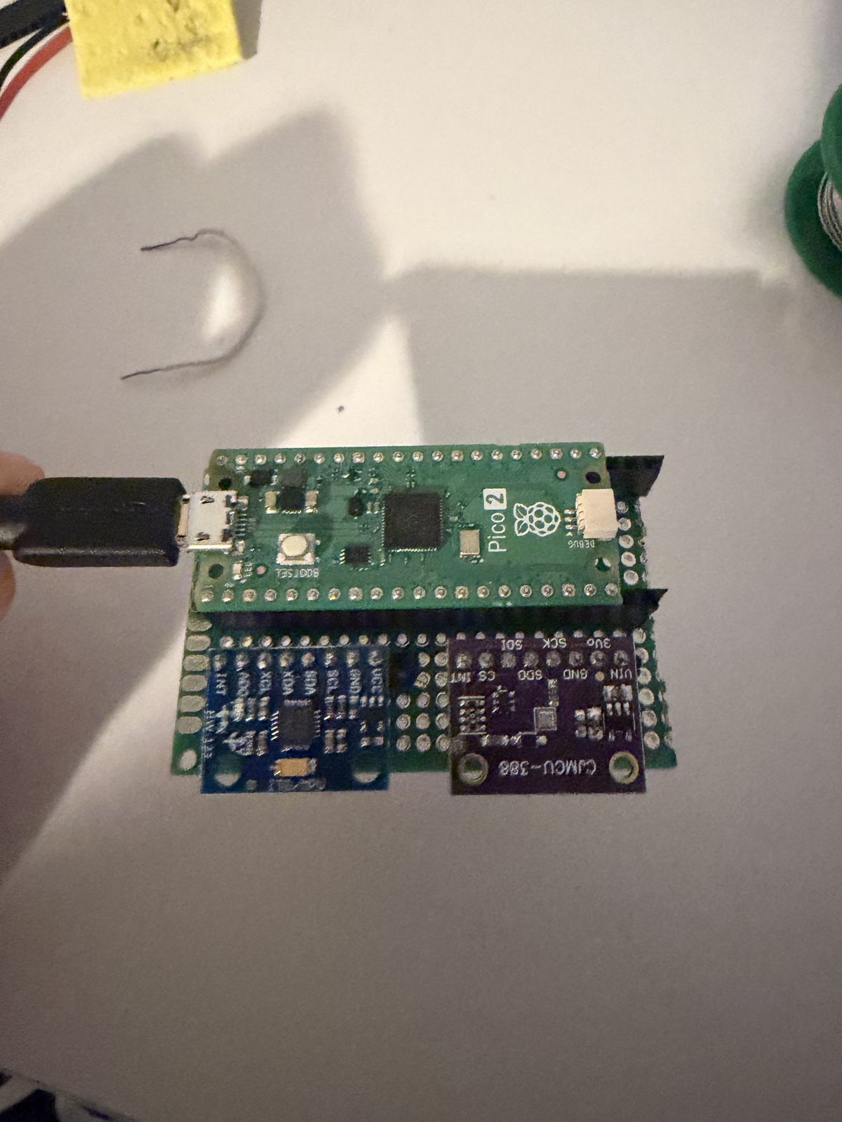
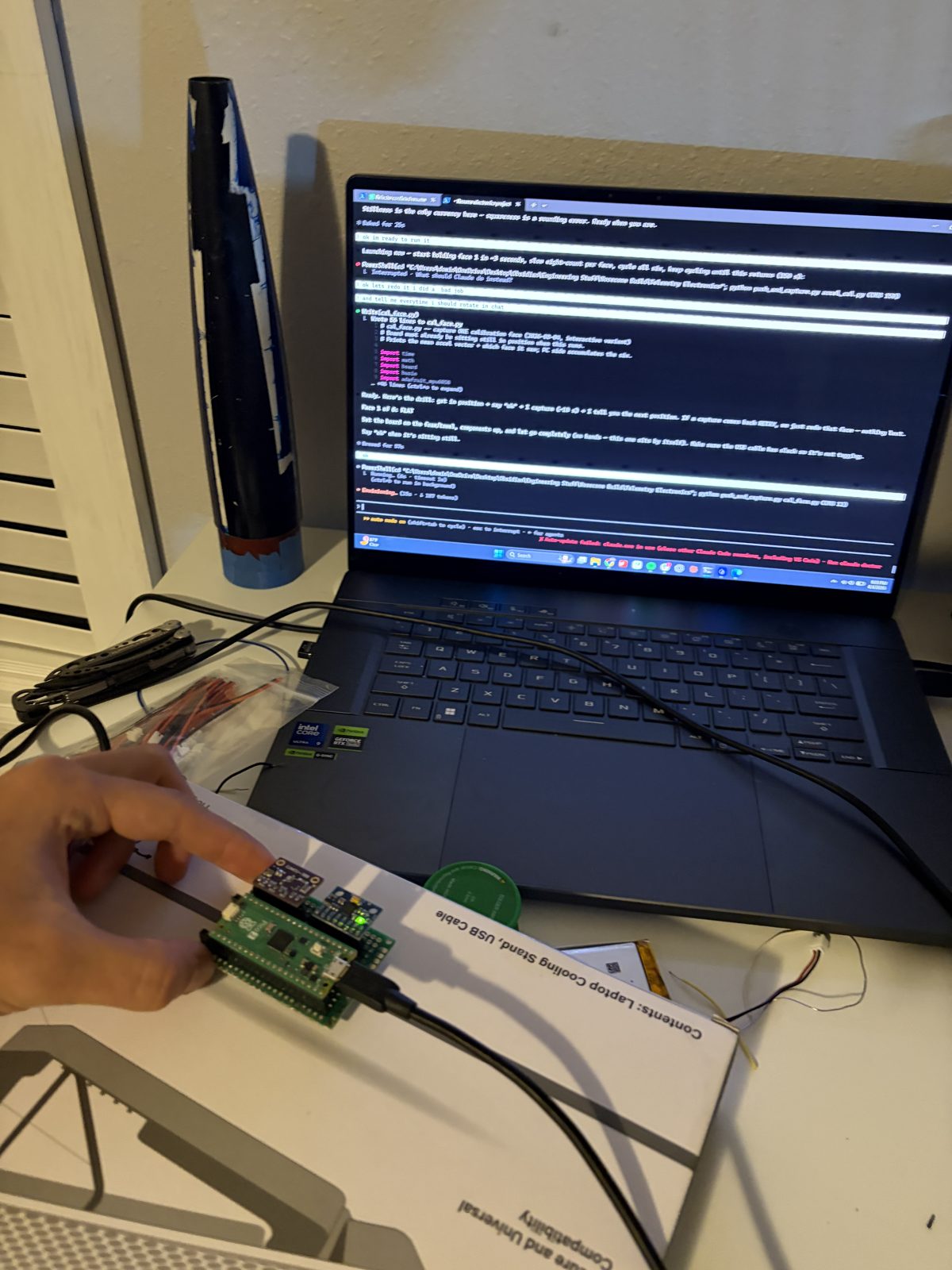
The soldered flight board with both sensors socketed, and the hardware-validation session over the USB console.
Overview
I built a flight computer from scratch so my rocket’s top speed and apogee would come from measurement rather than simulation: a Raspberry Pi Pico 2 with an IMU and a barometer, hand-soldered on perfboard, logging to onboard flash. Over this project I:
- Generated the perfboard wiring map
- Soldered the board and worked each bring-up bug to root cause
- Calibrated the accelerometer with a tilt-immune six-position solve
- Wrote and validated the flight firmware and log decoder
- Designed the printed housing and hardware assembly that carries the recovery load path
- Flew it twice
Goals & Requirements
- Log 100 Hz IMU and 50 Hz barometer data to onboard flash with zero sample skips
- Measure apogee barometrically and top speed by integrating boost acceleration
- Calibrate the accelerometer scale so it stops dominating the top-speed error budget
- Survive an unlimited pad wait without exhausting flash, and a hard landing without losing data
- Run self-contained on battery in the nosecone bay
Design & Build
Each quantity got the sensor that measures it best: the BMP388 barometer at 50 Hz for apogee (~0.13 m bench resolution), the MPU6050 accelerometer at 100 Hz for top speed over the ~2 s boost, and GPS parked as a recovery aid only.
The physical build was fairly simple with only minor wiring faults that could be fixed easily. Firmware and testing were written and performed with the help of Claude.
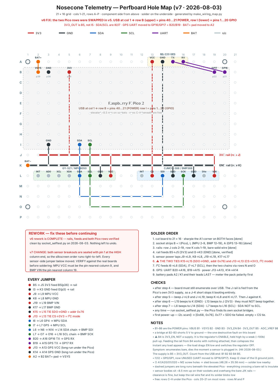
Generated wiring map v7 — the version I soldered from
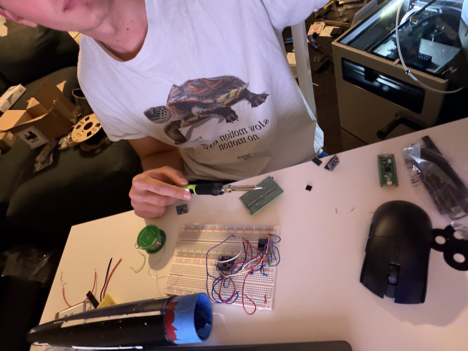
Bring-up, one sensor at a time
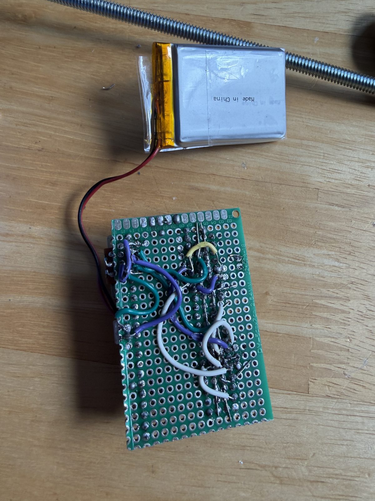
Solder side — point-to-point nets from the map
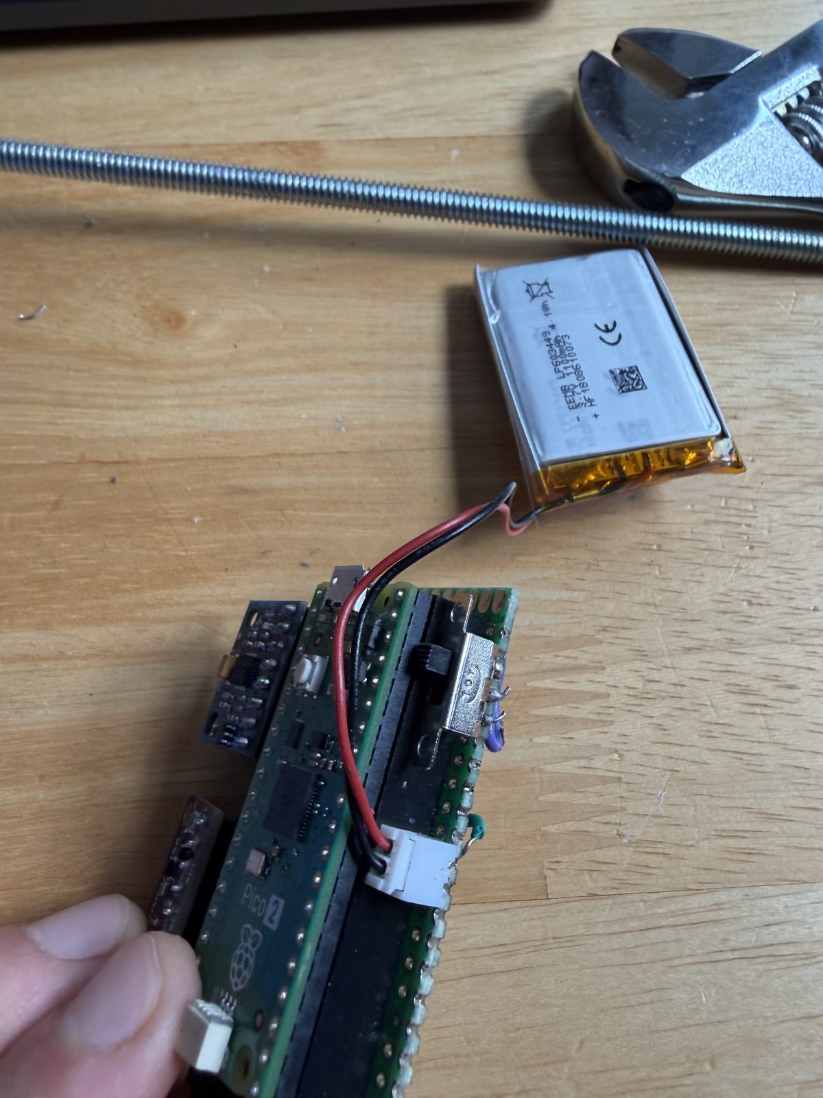
1100 mAh pack, JST header, arming switch
I calibrated the accelerometer on the finished board, in its ±16 g flight range, with a six-position solve on the magnitude equation |(a − b)/s| = g, so hand-hold tilt drops out of the math. That put the scale factor at ~0.2% against the ±3% datasheet bound, cutting its top-speed error contribution from ~4.5 m/s to under 1 m/s.
The firmware is built around the failure modes: pre-launch samples circulate in a RAM ring so an unlimited pad wait costs no flash, and fsync every 4 s after boost bounds what a hard landing can lose.
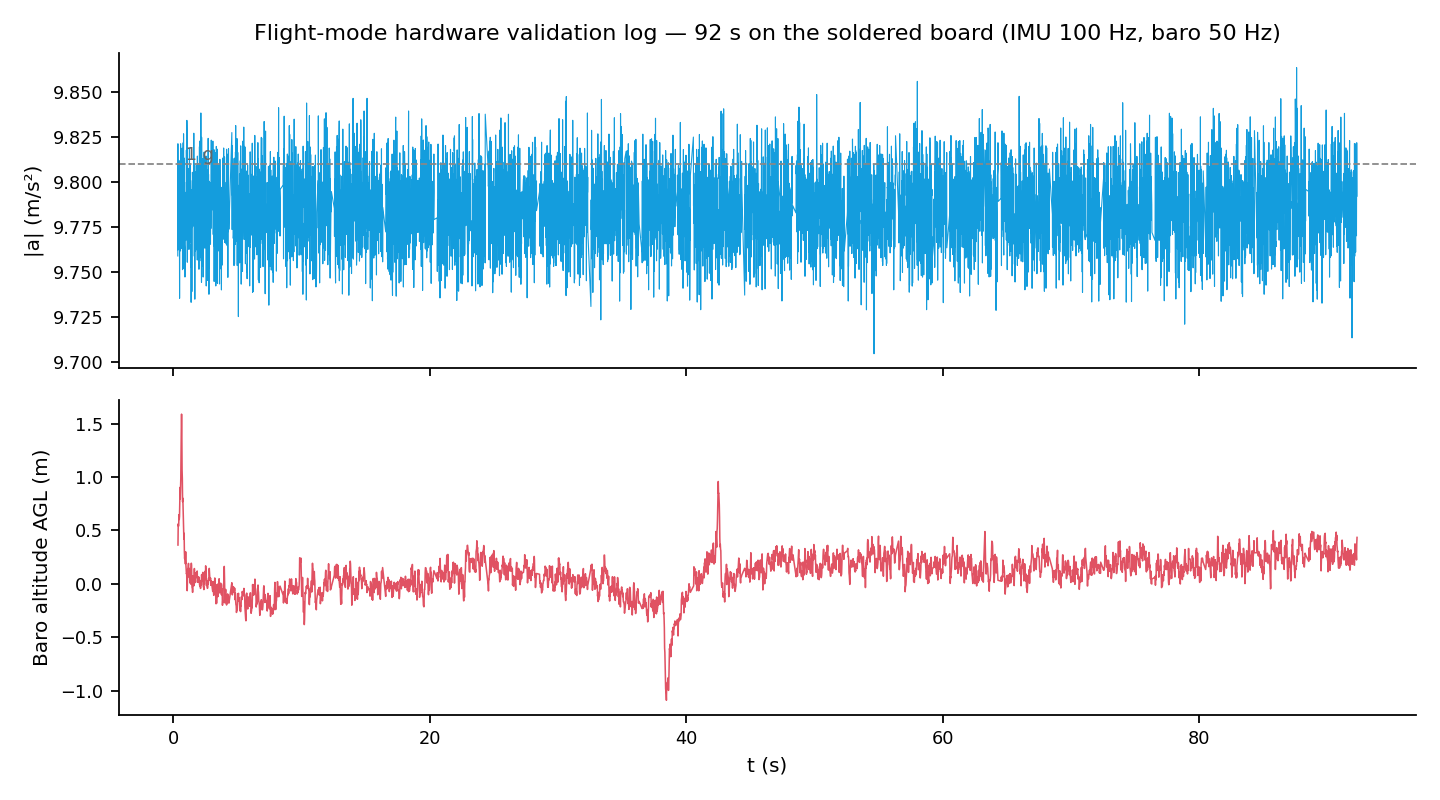
92 s hardware log — |a| at 100 Hz, baro at 50 Hz
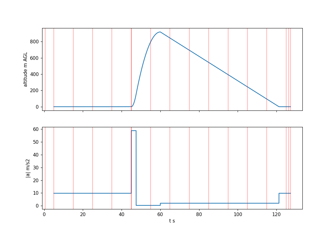
Synthetic regression — decoder vs. known truth
The printed housing carries the recovery load path — shock cord, eye bolt, base flange, lid screws, threaded rod into the nosecone tip — at a uniform SF ≈ 2 against the ~300 N deployment spike.
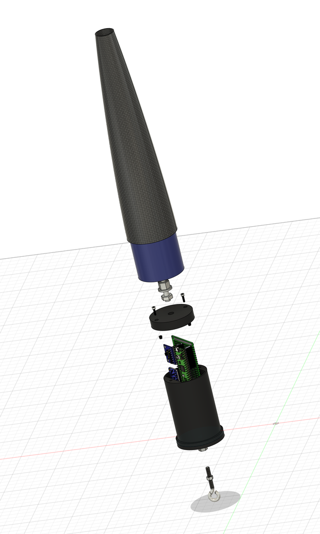
Exploded assembly — the recovery load path
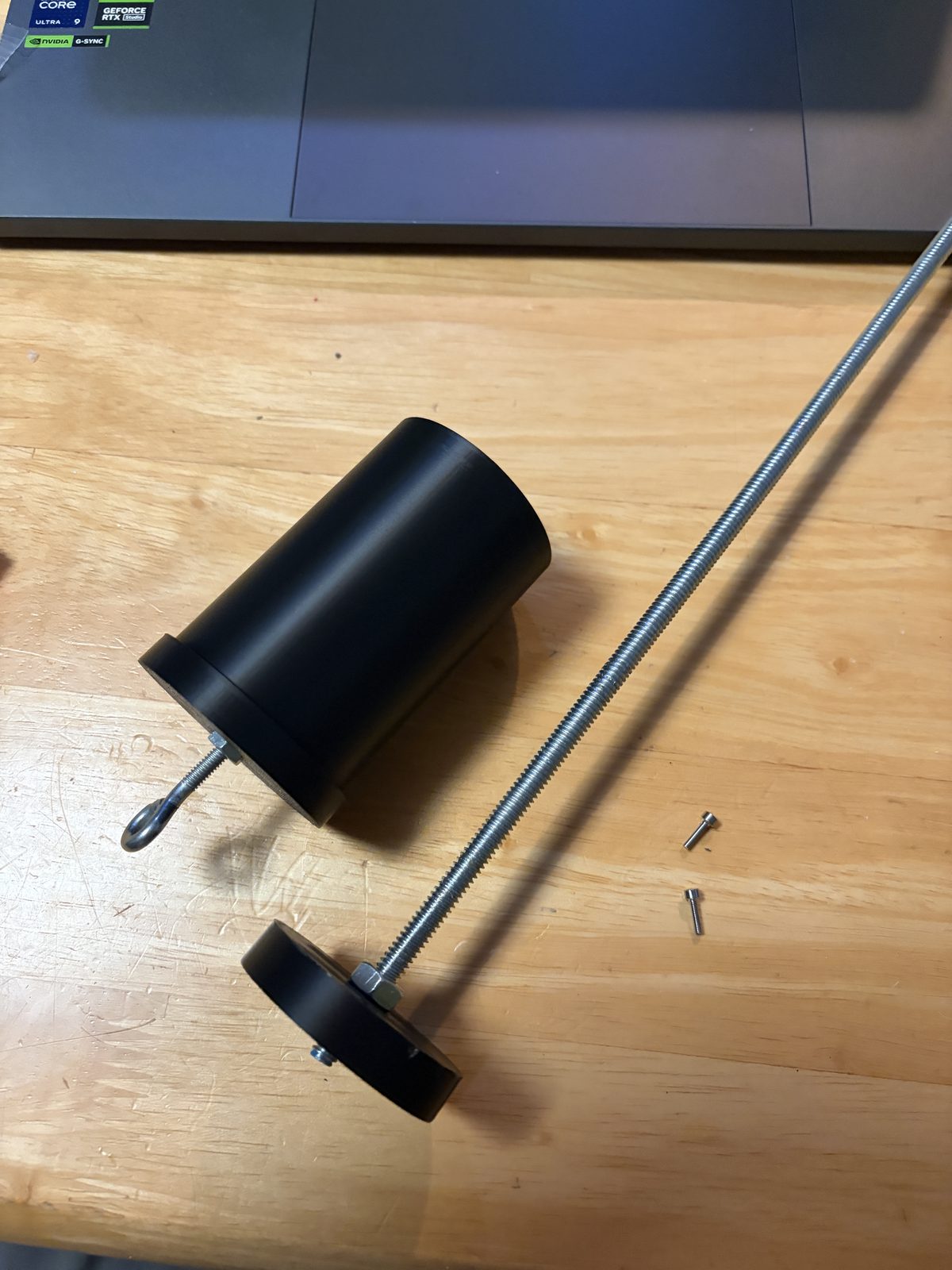
Housing assembled
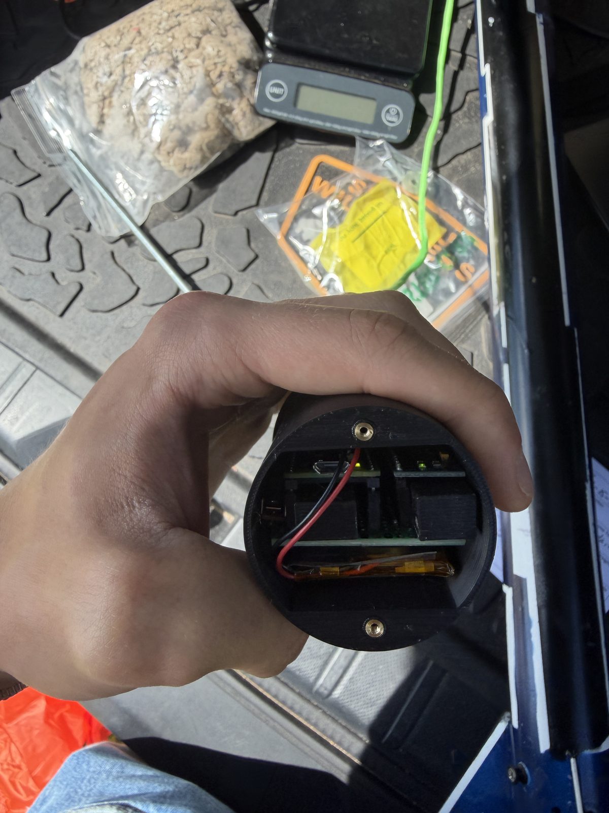
Board stack seated, ready to close out
Outcomes
- Flew twice on 15 Aug 2026: 100/50 Hz held through boost both times, with in-flight pressure cross-checks of +0.274 and +0.022 hPa
- The ±16 g range held with margin — 6 g boost (2.7×) and flight 2’s 15.5 g deployment shock captured unclipped
- Zero I²C errors through flight 1’s ballistic ground impact; the log survived a post-landing filesystem corruption by raw-imaging and carving the flash
- Top v2 change: finalize the log file at LANDED, closing the post-landing commit window that caused the corruption
This computer flew both flights of the campaign in the carbon nosecone it was built for.