
Retractable Keel Fin
Mechanical Engineering Internship — Levanta Technologies · Summer 2026
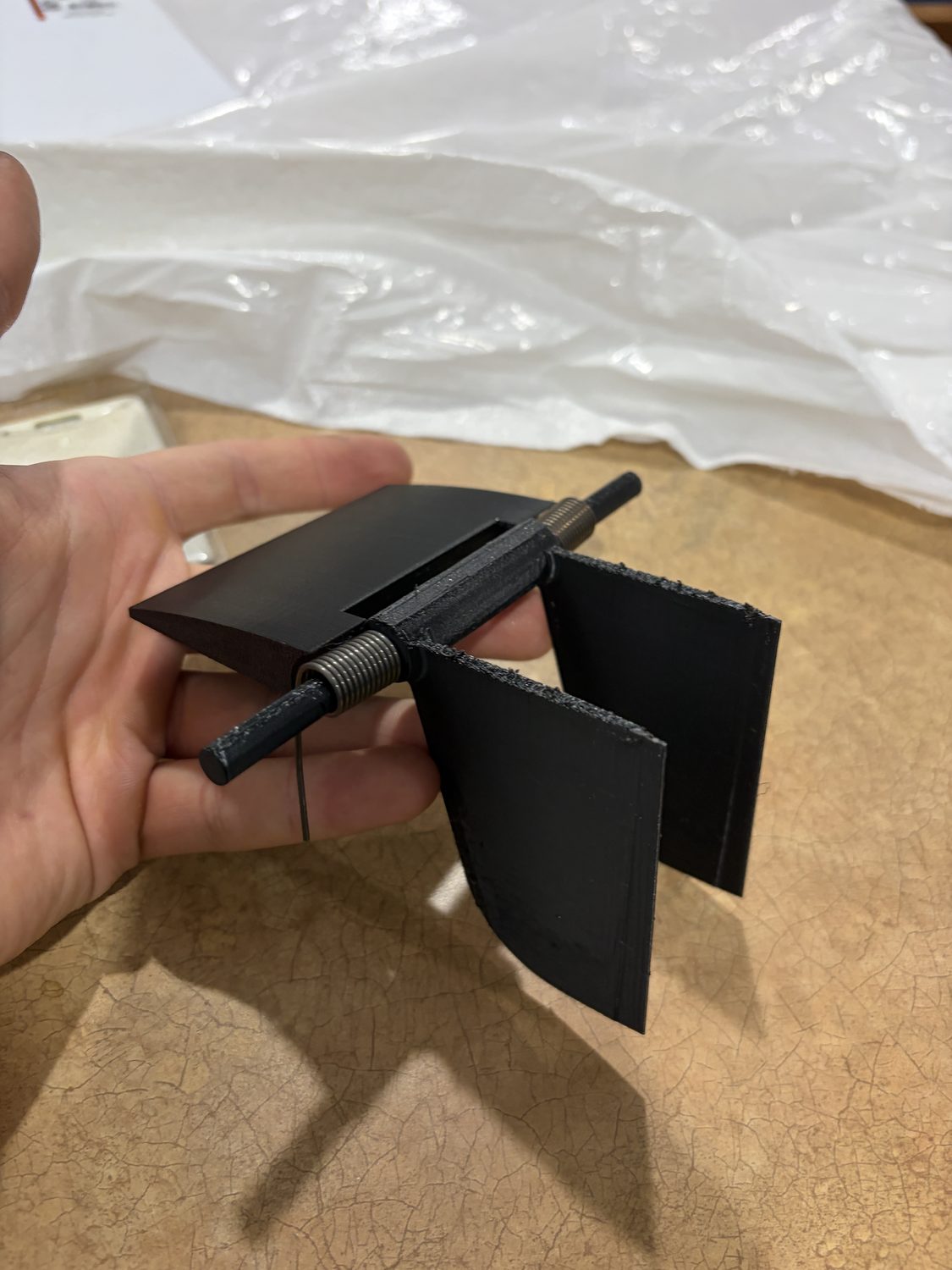
Final twin-fin design and kick-up demo
Overview
During my internship at Levanta Technologies, I designed a passive retractable keel fin for an autonomous maritime drone. The fin acts as a rigid yaw stabilizer at speed, but folds out of the way when the vehicle drives onto its recovery platform. Over the summer I:
- Developed the mechanism concept and load-path architecture
- Ran hand calculations and 2D/3D CFD in ANSYS Fluent to size the loads
- Sized the torsion springs using Shigley's method
- Designed the parts in Fusion 360 and built working printed prototypes
- Iterated through a design review and two redesigns to the final twin-fin configuration
Goals & Requirements
- Fully passive. No electronics, motors, or actuators
- Must not retract under normal drag load at up to 50 knots in saltwater
- Must retract when hitting the recovery platform
- Separate the drag force from the lateral stability force
- Ideally corrosion-resistant, and durable for long deployments in salt water
- Keep the specified NACA 16-006 airfoil and composite manufacturability
Design
The system was designed to decouple the lateral stabilizing load, and drag load. The fin mounts onto the back of the foils of the drone, and uses torsion springs in order to retract 80 degrees when resting on a recovery platform. Springs were sized (calculations below) so that drag force at 50 knots only retracts the fin by a maximum of 10 degrees at speed.
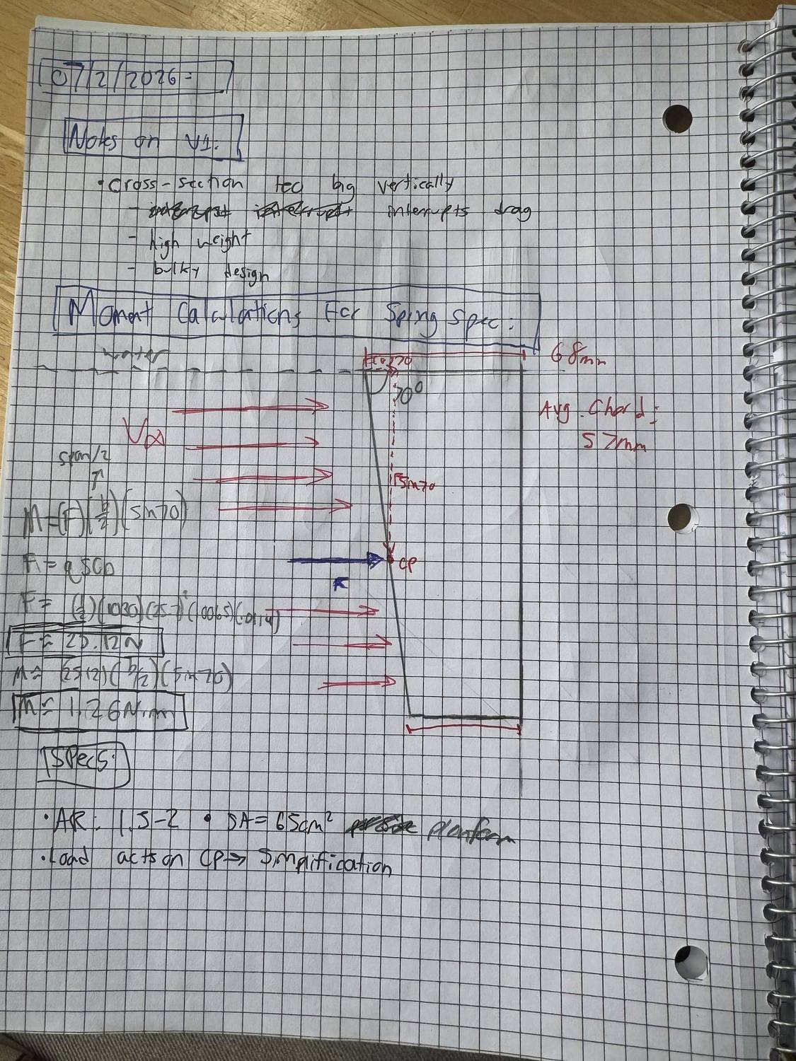
Hinge-moment hand calculation
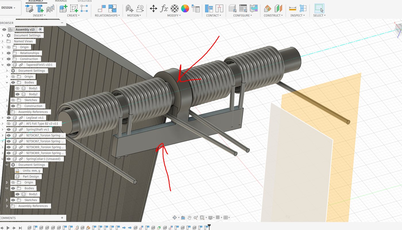
Matched LH/RH torsion springs flanking the keyed collar
I first estimated the drag by hand with a conservative assumed Cd of 0.10, giving ~220 N. To replace the guess, I ran a 2D simulation of the airfoil in ANSYS Fluent: NACA 16-006 at a 57 mm chord in seawater at 25.7 m/s (Re ≈ 1.4×10⁶), k-ω SST, with the wall resolved to y+ = 1.58. The result, Cd = 0.0111, 214 N per meter of span, 76% viscous, showed the hand estimate was ~9× conservative. The real hinge moment is about 1.3 N·m instead of 12, which is the difference between a spring that packages into the hinge and one that doesn't. As a sanity check, flat-plate skin-friction theory predicts a friction coefficient of 0.0087 versus the CFD's 0.0086 — a 2% match.
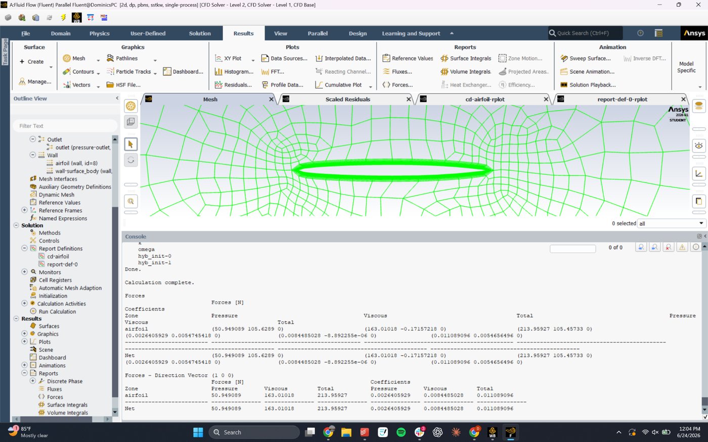
2D mesh in Fluent; converged force report: Cd = 0.0111, 76% viscous
The springs are a matched left/right torsion pair sized with Shigley's method, set at their free angle when deployed so they hold zero preload at rest and wind up through the 80° fold. The springs I ended up using are a bit too weak for full flight use and are not fully corrosion-resistant. Ideal springs would need to be manufactured in-house or custom-bought. I did not have this luxury, unfortunately.
v1 prototype demo
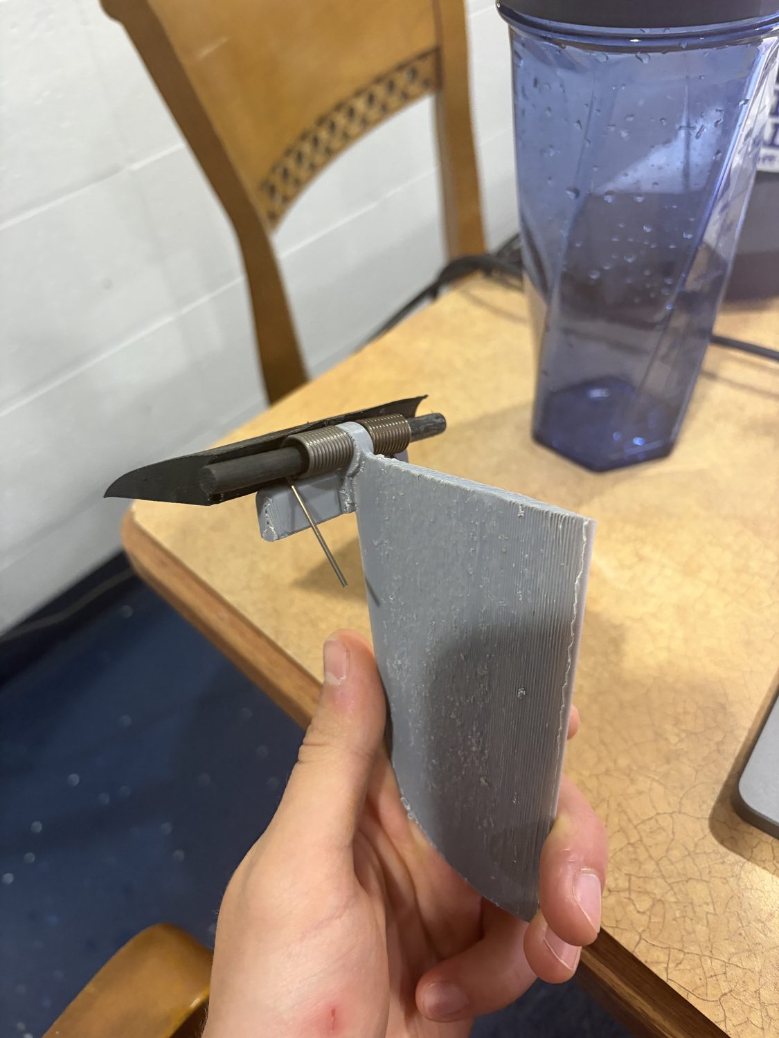
v2 single-fin prototype
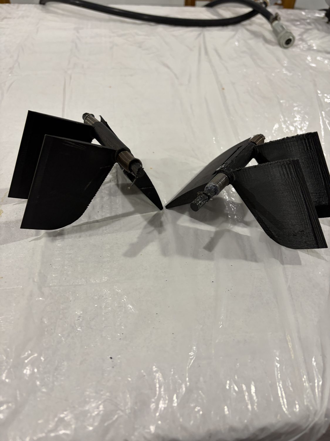
Final v3 twin-fin units
The design went through three major iterations. The first prototype initialized the torsion spring idea. A v2 prototype fractured at the blade root along a print-layer plane, which drove a reprint orientation change and a fillet at the neck that the final metal part keeps. After a design review, I split the single blade into two smaller fins — same total area, lower stress per blade, added redundancy — and removed all flow-disrupting features, including the crossbar, by bending the spring legs directly into the shaft.
Outcomes
- Working twin-fin prototype demonstrating the full fold–deploy–reset cycle
- Validated 2D CFD case (Cd = 0.0111, y+ = 1.58) and a 3D case with a documented fix list
- Spring specification and procurement path for the custom-wound pair
- Full design package handed off at internship end: parametric CAD, CFD cases, and calcs
Scope note: kinematics were proven on the bench; the design was handed off before vehicle integration or on-water testing.