
Bicycle Brake Caliper
Mechanical Design & Manufacturing (ME 240) — Northwestern · Spring 2026
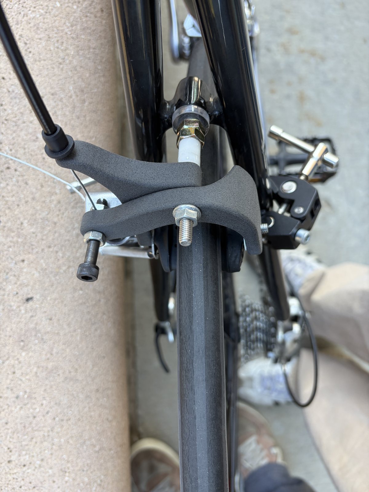
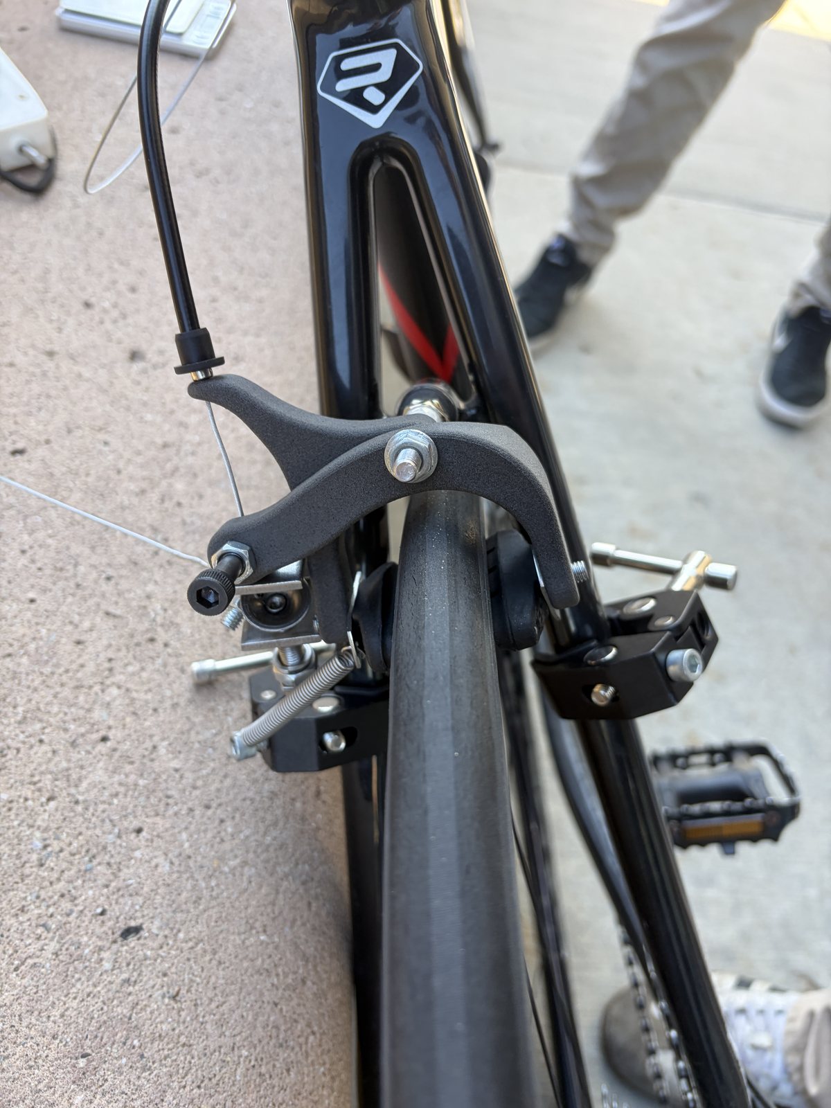
The redesigned Nylon 12 arms on the test bike, and the cable-side arm.
Overview
For ME 240 our four-person team designed a single-pivot, side-pull brake caliper for the rear wheel of a real test bicycle, printed in SLS Nylon 12. I was testing & validation lead and FEA & topology lead, and redesigned both arms for the final version. Over the quarter I:
- Ran the hand analysis — energy balance, moment balance, and section sizing at the arm root
- Ran a topology optimization on the design-space solid to generate the initial arms
- Meshed and solved both arms in NX Nastran
- Redesigned both arms after the first road test failed
- Ran the road-test program against the ISO braking-distance requirement
Goals & Requirements
- Fit the constrained design space around an actual frame and rim
- Transmit cable tension into pad clamping force, then release cleanly
- Stop the bike within the braking distances of ISO 4210-2 / 4210-4 — 7.62 m adjusted to our test speed
- Keep peak stress under Nylon 12’s ~50 MPa ultimate strength
- Keep total deflection under 11 mm so the lever can’t bottom out on the bar
Design
Hand analysis came first. An energy balance (d = v²/2μg) set the rim friction the pads have to generate, a moment balance about the pivot set the lever ratio, and σ = P/A + Mc/I sized the sections at the arm root — and correctly predicted where FEA would later find the peak stress, which is why I trusted the mesh.
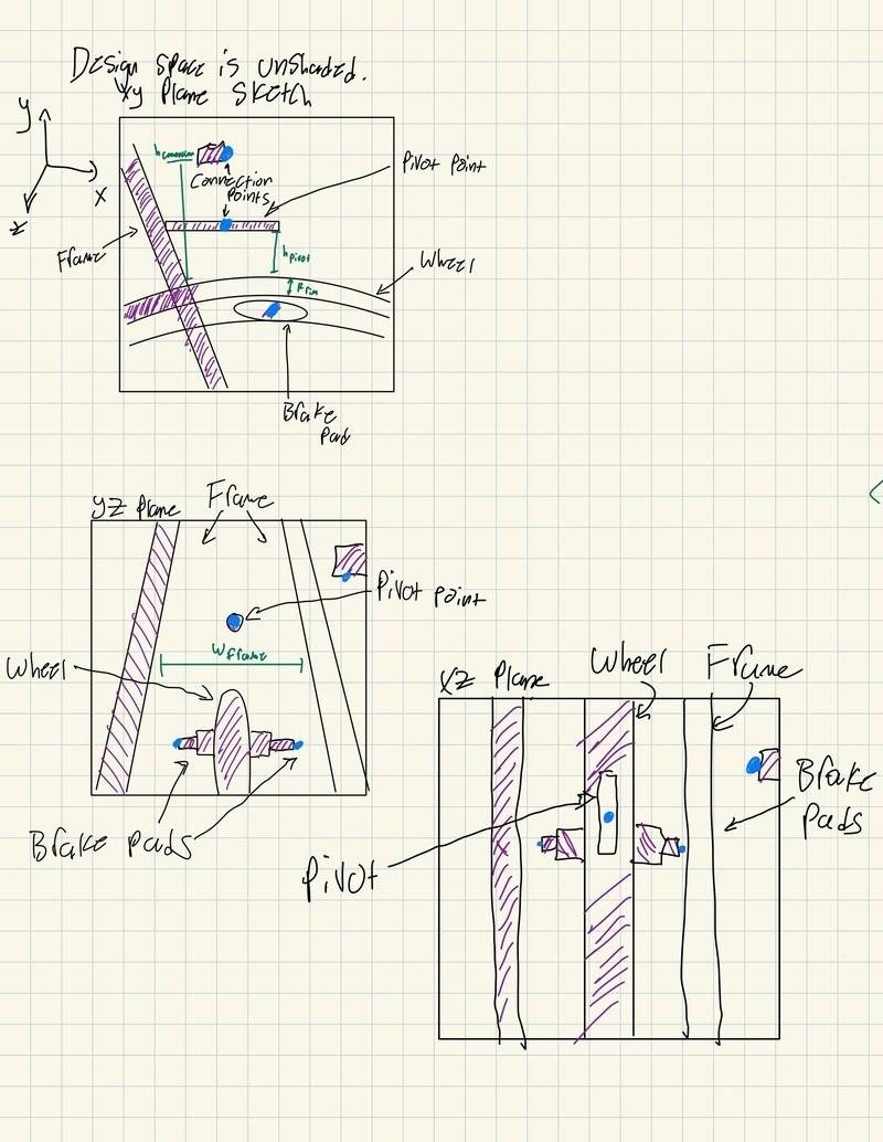
Design space in three planes
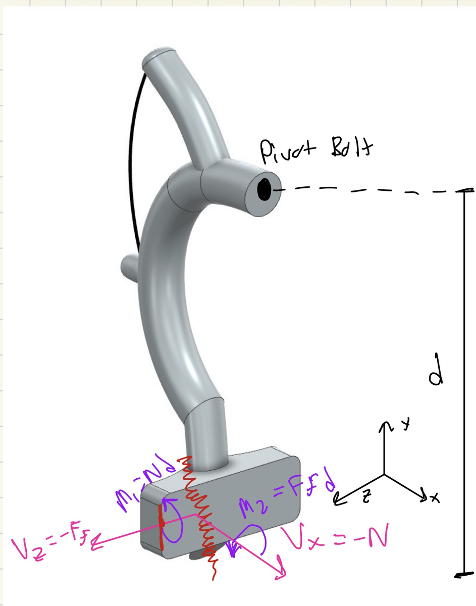
Internal moments at the arm root
The initial arms came out of a topology optimization I ran on the design-space solid. Each arm was meshed and solved separately in NX Nastran — constrained at the pivot and mounting interfaces, loaded with the 89 N (20 lbf) cable force, stress read as unaveraged von Mises with constraint singularities excluded. That design passed on paper: 45.12 MPa peak on the left arm, 48.66 MPa on the right, 8.953 mm total deflection.
It failed the first road test anyway. The print was built around incorrect bike design-space dimensions, so the pads rubbed at rest and never contacted the rim squarely. I redesigned both arms around the verified geometry: pads meeting the rim flat and symmetrically, thickened root sections, a reoriented cable hole, and hardware clearance. The redesign also improved the numbers: peak stress fell about 16%, to 41.17 MPa on the left and 40.81 MPa on the right, and total deflection dropped from 8.953 mm to 7.581 mm against the 11 mm limit.
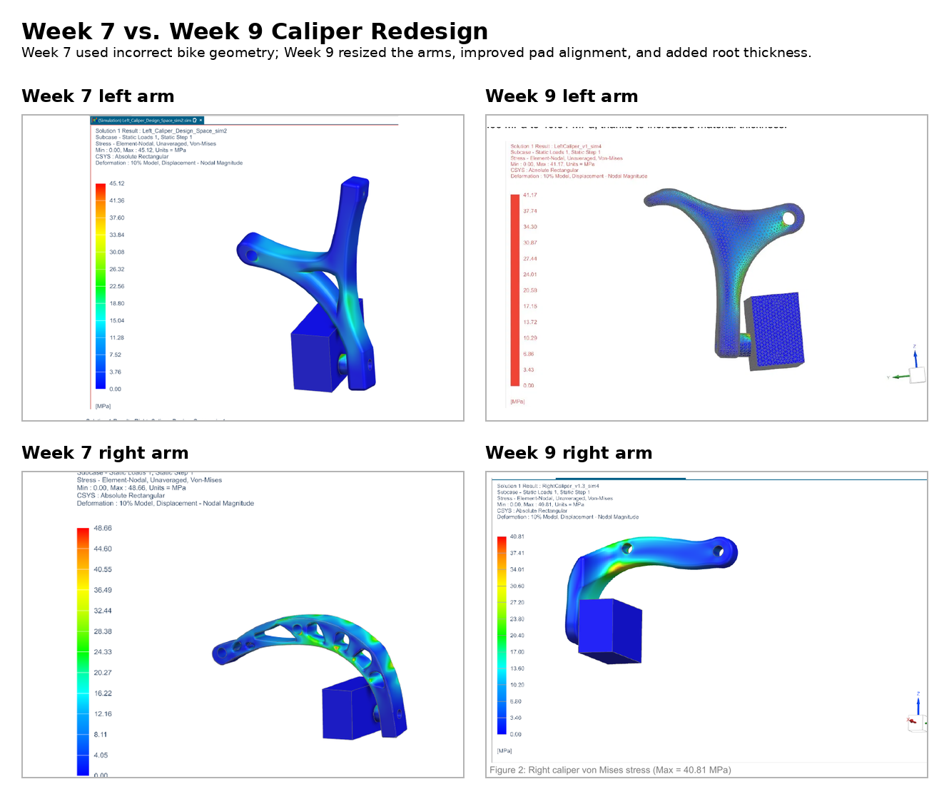
Initial vs. redesigned arms, same load case
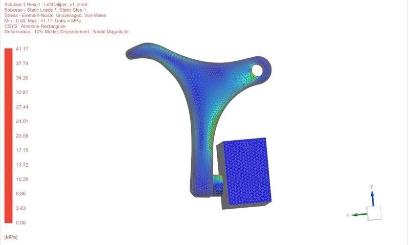
Redesigned left arm von Mises — max 41.17 MPa
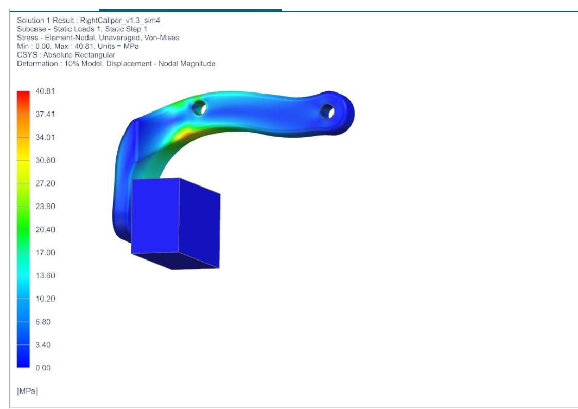
Redesigned right arm von Mises — max 40.81 MPa
As testing lead I ran the validation — a rider braking as hard as possible from a stop line — with the stop distance corrected to the ISO 4210-2 reference speed by dmax = dISO(vtest²/vISO²). The redesigned caliper stopped the bike in 5.334 m against the 7.62 m allowable, at 40 g per arm and 140 N actuation force. A Granta EduPack screen selected 7075-T6 aluminum for production, and a fatigue check (Basquin S-N with Marin factors) showed the Nylon 12 part is a finite-life prototype.
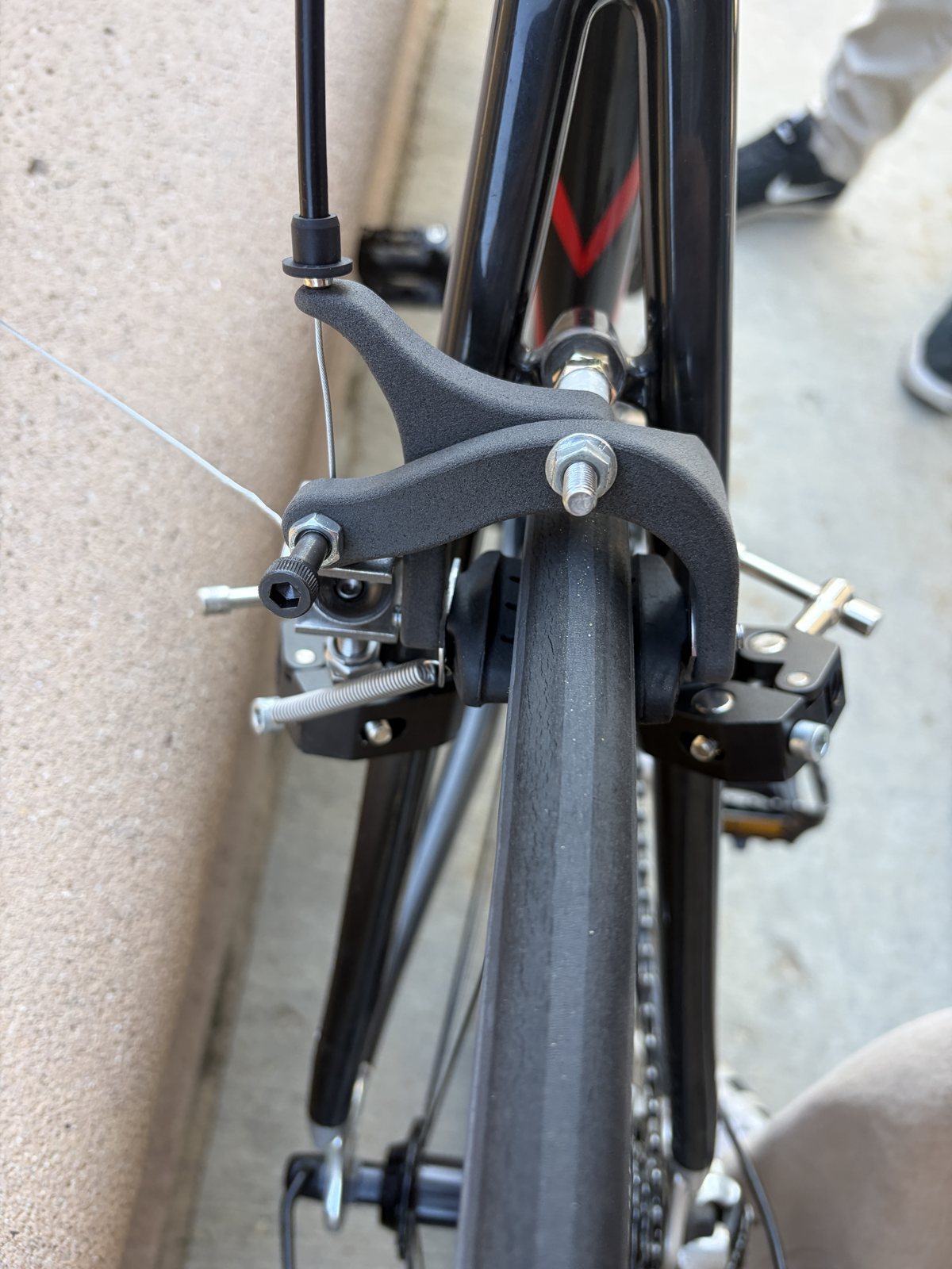
Both printed arms installed, and the braking run that produced the 5.334 m stop.
Outcomes
- Road-test pass: 5.334 m stop against the 7.62 m ISO-adjusted limit
- Peak stress after the redesign: 48.66 → 40.81 MPa (right arm, ~16% lower) and 45.12 → 41.17 MPa (left); deflection safety factor 1.23 → 1.45
- 7075-T6 aluminum selected as the production material
- Three requirements still fail: overall width 60.6 mm vs 55, released pad clearance 0.05 mm vs 0.3–2.0, adjustment range 1 mm vs 2
Scope note: the printed caliper is a finite-life prototype. The FEA numbers are static checks against the ~50 MPa ultimate, no fatigue calculations involved.